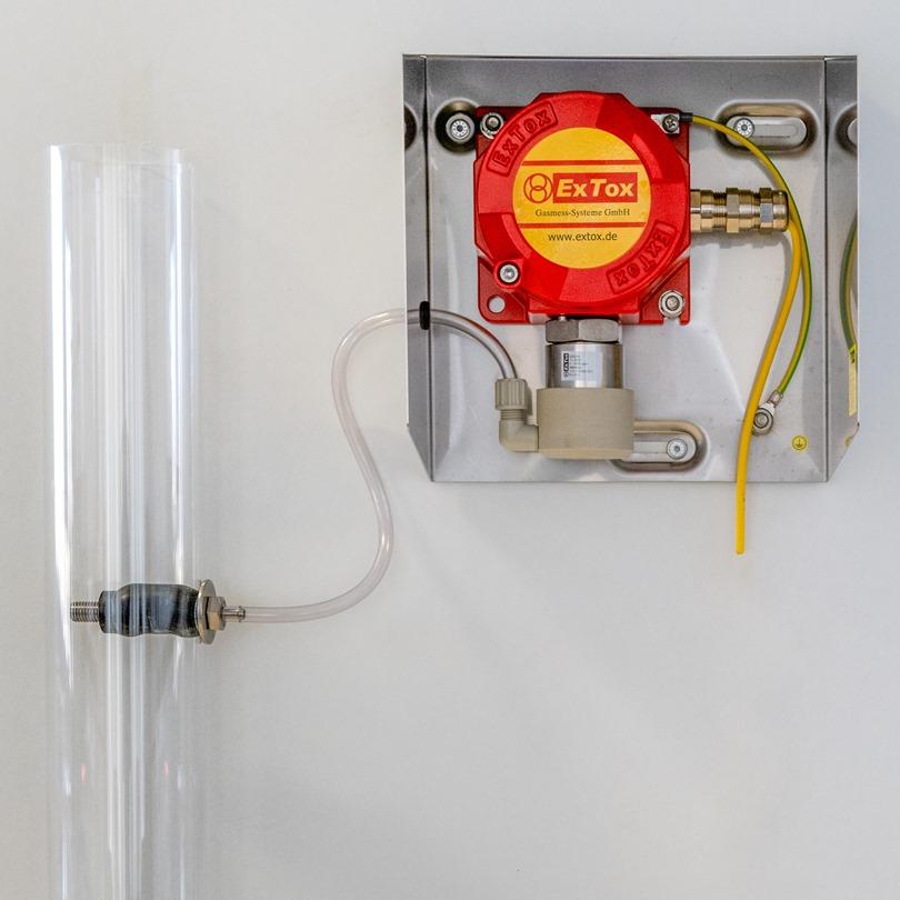
Monitoring of air inflated membrane systems at Biogas Plants.
Cost efficient solution for membrane systems with dynamic pressure at the blow-off end. Early recognizing of leakages, in order to avoid cost due to gas loss and danger for staff, plant and environment.

Description
-
Measuring Range: 0 to 5000 ppm Methane
-
Measuring Principle: Metall oxyde Semiconductor
-
Operation Mode: Continuous Measurement
-
Sampling of measured gas: Difference in (dynamic) pressure inside the air inflated system
-
Difference(dynamic)Pressure: ≥ 2 hPa (mbar) and ≤ 10 hPa (mbar)
-
Maximum distance to the measured gas suction point: ca. 1.5 m
-
Connection to measuringConnection to measuringpoint:
· Self-sealing EPDM-rivet-hose adapter
· PE-Hose 6/8 mm, 2 m (cannot be lengthened)
· TL-Measuring adapter for transmitter
-
Evaluation measuring signal: ExTox Control Unit or ExTox IMC
Range of Application
-
Temperature: -20 °C to 55°C
-
Humidity: 10 r.H to 90 r.H (avoid condensation)
-
Pressure (surrounding atmosphere): 800 hPa to 1100 hPa
-
Weather protection: Stainless steel cover (part of the scope of delivery)
Installation Hints
-
The measured gas suction point has to be in air flow direction before the dynamic pressure flap. In comparision to atmospere the dynamic pressure has to be miminum 2 hPa (mbar) and not more than 10 hPa (mbar) at this point.
-
The Transmitter TL-5000-STD is installed closed to the blow-off opening. For protection of the transmitter against atmospherical influences, especially direct sun, a weather protection cover is installed. By this a stable measuring behaviour is ensured even on those small methane concentrations. The weather protection cover might not be removed.
-
Conneciton of the measuring gas feeding to the transmitter is done by means of a self- sealing EPDM-rivet-hose adapter which is easy to install. Only a drill hole of 24 mm is necessary on the exhaust line. The gas transport to the sensor is ensured by dynamic pressure at the blow-off end. A gas suction pump is not necessary.
-
The (non-insulated) measured gas line has to be laid ascending on a minimum length of 30 cm behind the suction point; see Installation Hints on Page 3. It is allowed to shorten the supplied measured gas line, but it might not be lengthened.
-
The Transmitter TL-5000-STD has to be installed accessibly for maintenance work.
Mechanical Data
-
Weight: approx. 4 kg
-
Material:
· Housing: cast aluminium, lacquered
· Sensor block and weather protection: stainless steel
-
Enclosure Rating: IP 65 (except gas inlet)
-
Storage Temperature: -25 °C to +60 °C
Electrical Data
-
Power Supply: 24 ± 6 V DC
-
Power Consumption: 80 mA / 2 W
-
Interface:
· 4…20 mA, active
· Linear calibration curve
-
Max. Load: 500 Ω
-
Cable Gland: M 16 x 1.5, diameter of cable 4-8.5 mm
Conformity
-
EC-Directives:
· 2014/30/EU (EMC)
· 2014/34/EU (ATEX)
-
Type examination Test: BVS 04 ATEX E 066 X (EN 60079-0 und EN 60079-1) incl 1. and 2. Amendment
-
Protection: Ex db IIC T4 (-20 °C ≤ Tamb ≤ 60 °C) Gb
-
Measuring Functions:
· Measurement technical features designed for detection of small increases of concentration for early recognition of leakages
· Functional features according to Requirements to Gas detection systems DIN EN 60079-29-1
Further applicable Documents
-
Instruction Manual ExTox Transmitter ExSens(-I) and Sens(-I)
-
Data Sheet Transmitter Series ExSens and Sens: General Installation Hints
(Subject to Technical Changes)
All control units of the ET-Series could be used in combination with all ExTox Transmitters ExSens(-I) and Sens(-I)
Our control units in combination with the ExTox Transmitters comply with the requirements of EN 60079-29-1, EN 45544-1 to EN 45544-3 and EN 50104 for Gas Detection Systems. Furthermore are those in conformity to the European Directives 2014/34/EU (ATEX), 2014/30/EU (EMV), 2014/35/EU (LVD).
Downloads
Here you can download detailed information about our products, applications and systems